Sensor Connectors
Categories
- Card Edge Connectors
- RECTANGULAR CONNECTORS
- D-Sub Connectors
- Machined D-Sub Connectors
- Power Combo D-Sub Connectors
- Parallel Port D-Sub Connectors
- Waterproof D-Sub Connectors
- DB9 Connector
- DB15 Connector
- DB25 Connector
- Vertical PCB D-Sub Connector
- D-Sub Panel Cut-outs
- Cable Wire D-Sub Connector
- PCB D-Sub Connector
- Right-angle PCB D-Sub Connector
- Backshells or Hoods, and Caps for D-Sub Connectors
- D-Sub Connector Housings
- D-Sub Connector Contacts
- Modular & Magnetic Jacks
- USB Connectors
- HDMI Connectors
- INLINE CONNECTORS
- HEADER CONNECTORS
- Spring Loaded Connectors
- Waterproof Connectors
- Cable Assemblies
- Custom Connectors
Stocking Distributors


Search Parts:
Engineering Connector Considerations for Sensor Applications
Sensors are necessary to track and monitor systems in a slew of applications from residences and buildings to industrial equipment, in more traditional supervisory control and data acquisition (SCADA) systems, and Industrial IoT (IIoT). Sensor technologies are also found in mobile applications such as automotive vehicles and aircraft to ensure safe operations and a smooth ride. Sensors are also required to simply collect data for research and development (R&D) purposes for prototype development. There are innumerable applications that rely on sensors to operate; however, the sensors themselves rely on their interconnect to be able to transmit these critical signals in real-time through a wired or wireless backbone.
More often than not, sensors are translating physical phenomena into electrical impulses that can be interpreted by a local processor and relayed back at a source for analysis and control. The physical phenomena can be a pressure measurement from a passing liquid or an acceleration/deceleration measurement from movement. One key connector design challenge to consider in these sensor applications is that the connectors will undergo the very same stressors. However, it is the job of these components to take the data from sensor modules and transmit them to their intended location despite the environmental or mechanical “beating” they may be taking. This article describes the engineering considerations required for sensor applications.
Sensor types and measurements
Table 1 shows an overview of sensors and the measurements they collect. There is a wide variety of sensor types to match with the needs of the applications. However, there is a great deal of overlap between the sensor technologies used in many embedded systems.
Sensor types and their measurements
Sensor Type |
Measurement |
Sensor Type |
Measurement |
|---|---|---|---|
|
Gyro Sensor |
Angular velocity |
Flowmeter |
Liquid flow |
|
Accelerometer |
Vibrational data |
Acoustic Sensor |
Seismic data |
|
Motor Current Signature |
Current and Voltage data |
Pressure Sensor |
Pressure data |
|
Hall-effect Sensor |
Magnetic field strength |
Level Sensor |
Liquid level data |
|
Temp Sensor |
Temperature data |
Gas Sensor |
Gas concentration |
|
Humidity Sensor |
Humidity data |
Current Sensor |
Current data |
Table 1: Sensor types and data gathered from the respective sensor.
Some of these sensors will measure mechanical phenomena, such as an accelerometer to measure acceleration/deceleration and mechanical shock on all three axes or a gyro sensor to measure angular velocity or the speed of rotation. Other sensors will measure environmental factors such as temperature, humidity, pressure, liquid level, and gas detection. Sensors will also measure electrical/electromagnetic parameters to ensure the nominal operation of the system. Current sensors are widely used in power supplies found in many types of applications for power management, such as automotive systems (e.g., main drives, OBCs, power train), or in motor-based applications to detect the current in the motor and employ various algorithms for synchronization and orientation of the motor. Hall effect sensors will detect the presence, motion, and field strength of a magnetic field from, for instance, an electromagnet. They are often used in brushless DC (BLDC) motors to detect the position of the rotor.
Sensor technologies are often micro-electro-mechanical systems (MEMS) to save space and increase device reliability. The classic example is the capacitive-based MEMS accelerometer, which uses a proof mass suspended between springs that are generally two electrodes where one of them is movable. The mass will displace in response to an external acceleration between these capacitive displacement sensing structures (e.g., parallel plates, interdigitated fingers) yielding an electrical potential (i.e., voltage) that directly correlates with an acceleration rate and acceleration direction. These sensor technologies are often implemented for their small size and cost-effectiveness; they can be mounted within small enclosures and easily embedded within a system to feed data back to a more central processor. The data will often travel to its source via connectors and cabling.
A few rugged sensor applications
The common underlying theme with all applications that use sensors is that mechanical, environmental, and electrical variations are actively measured and therefore the entire device, or sensor module, will likely be subjected to these strains. In IoT applications such as home automation, measuring temperature via a remotely controllable thermostat may not be a particularly rugged application. However, there are many applications that are quite harsh for the electronics and connections of the sensor module.
Machine health monitoring in industrial applications, for instance, will require the continuous, real-time data of induction motors in CNC machines, industrial cranes, pulleys, or heavy-duty mixing tanks. Any faults in the motors can greatly degrade mechanical accuracy or cause equipment failure. Equipment failure can lead to factory downtime, and this comes at great cost to the manufacturing facility. Latest information suggests that factory downtime costs as much as $50 billion annually — 42% of which stems from equipment failure [1]. The exorbitant cost of downtime has been a driving factor behind IIoT, in an attempt to gather all plant data and use analytics to perform predictive maintenance ― an avenue to predict maintenance and faults well before they occur. Industrial facilities have had stringent systems in place for functional safety in order to protect personnel. Control-systems engineers have always put together industrial systems where reliability is key, using probability of failure for all components in a safety instrumented system (SIS) to ensure a particular safety integrity level (SIL). In order to ensure industrial machines are functioning nominally, a similar level of scrutiny should go into the components within a machine and its sensor system.
Transportation and automotive sensors also require a great deal of reliability. Automobiles will have highly embedded sensors to monitor every aspect of the vehicle's health. This includes airbag sensors, parking sensors, the tire pressure monitoring system (TPMS), fuel temperature sensor (FTS), wheel speed sensor, and the many sensors needed for the engine control unit to optimize vehicle performance (e.g., oxygen sensor, mass airflow sensor, knock sensor, crankshaft position sensor). Heavy-duty equipment requires many of these sensors as well as additional sensors to ensure the pneumatic, hydraulic, and other mechanical (motor-driven) systems are functioning properly. Hydraulic sensors in an excavator, for instance, can be placed at predetermined locations within the boom, stick, and bucket to measure hydraulic actuator pressures and their corresponding hydraulic pump pressures. Another more niche automotive application is race cars where data must be collected live and in near-real-time. Figure 1 shows the live telemetry logged from a formula-style prototype vehicle made by the University of Waterloo. The data is also recorded by a data logger in order to be pulled offline for further analysis.
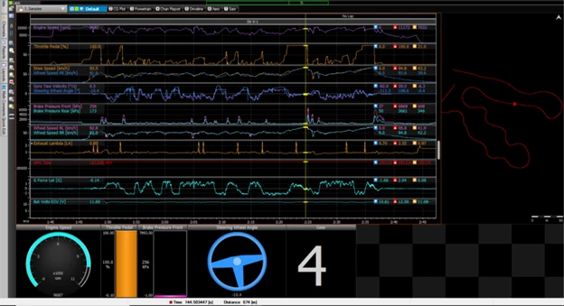
Figure 1: Live telemetry from embedded sensors on a formula-style race car, the connectors installed must reliably relay sensor data for data-driven analysis and tuning.
Table 2 shows the sensors used within the use case of a formula-style prototype vehicle for research purposes. It highlights the high utility of sensor data and how necessary it is to receive vehicle information without malfunctions of the sensors and its connectors.
Sensor types and their measurements for formula-style race cars
Sensor Type | Measurement | Application Description |
|---|---|---|
Laser Ride Height Sensor | Distance from underside of chassis to ground and tire compression data | Useful on high downforce cars to ensure car is within a preferred ride height range |
Hall-effect Sensor | Rotation data (wheel, crankshaft, and camshaft speed/position) | Used to analyze driver performance; cam/crank sensors feed ECU data to trigger injectors, set engine RPM, and rev limit |
Steering Potentiometer | Measures whether understeer/oversteer is chassis- or driver-induced | Data collected can be used to compare the effectiveness of multiple drivers |
Damper Potentiometer | Range/rate of wheel movement | Used to optimize the setup of the chassis |
GPS | Measure car position on track | Improves lap times, tracing driving times |
Lap Beacon Sensor | Lap-time recording | Records lap times |
Pressure Sensor | Pressure data for brakes (max brake pressure applied, braking points) and engine (air intake) | Useful for engine tuning for safety purposes and for driver analysis |
Temperature Sensor | Temperature monitoring for engine parameters, brake temperature, and tire-surface temperature | Keeps brakes and tires within preferred operating window |
Lambda Sensor | Measures unburnt oxygen present in exhaust | Used to adjust air/fuel mixture in engine |
Gyroscopic Sensor | Measures rotational acceleration | Used to show a rate of change of direction |
Table 2: Sensors used in a formula-style vehicle.
Design challenges of sensor systems
As described earlier, these sensors can be subject to:
- Constant vibration
- Extreme temperature variations (thermal shock)
- G-forces (e.g., mechanical shock)
- Humidity
- Salty atmospheres
- Moisture ingress/immersion
These stressors can quickly cause a connector assembly to fail. The following sections will discuss the failure mechanisms of these various strains and connectors that have been ruggedized to withstand them.
Vibration, mating cycles, and mechanical shock considerations
Mechanical shock is defined as a sudden acceleration. This can be caused by an impact, such as being stepped on by a person, a collision with another object, or by dropping the device. Such shocks are, by definition, transient physical phenomena and are therefore generally not as detrimental as vibration. However, it is important to consider. Devices and connectors that are resistant to vibration are often resistant to most mechanical shocks.
Vibration, for instance, can cause connector heads not suited to the environment to unmate, this is especially the case with connectors that do not use a mating mechanism with a high retention strength (e.g., screw-lock, bayonet-type mating). However, the most common failure mode for vibration occurs within the connector head and at the pins ― while the connector head is held in place the cyclic movements from vibration cause the surfaces of the male and female pins to begin rubbing against one another, causing what is known as vibration fretting. This removes the surface material from one pin and transfers it to the other, and since pins are often plated with corrosion-resistant malleable metals such as gold, these materials will get rubbed off first. The rubbed-off debris and freshly exposed metal surface will experience oxidation and more surface roughness, which in turn accelerates the wear and tear from vibration. This will eventually lead to failure. This also occurs with other types of abrasive motions, such as mating and unmating. Frequent mating cycles can cause these types of failures as well. Board-to-board connectors are especially susceptible to this as the rigidity of the overall structure does not allow for much movement. Wire-to-board and wire-to-wire connectors are less susceptible to fretting corrosion.
In order to mitigate the effects of fretting corrosion, it is important to use contact designs that can float when mated; in other words, a mate that allows for some micro-movements to occur. This requires contacts that are precisely machines. Another major consideration for high-vibration environments is ensuring that the mate is free from contaminants, as these particles can cause serious wear to the gold-plating and accelerate fretting. In high-humidity environments, it is also possible for the contaminant to remain on (or embed into) contact surfaces, further aggravating the connection [2]. Another consideration is the plating thickness (30µ” or more); pins with a higher plating thickness can help slow down the effects of fretting, as gold is a corrosion-resistant material.
Moisture ingress, salty atmospheres, and humidity considerations
High humidity and moist environments have been known to induce several failure modes for electronics that need to be avoided through proper ruggedization. Some of these failures include [3]:
- Hygroscopic swelling
- Electrolytic corrosion
Polymers often used in connectors such as epoxies, thermoplastics, silicones, and various dielectrics will often experience a volumetric expansion in the presence of moisture — this is known as hygroscopic swelling. As the moisture level increases, the materials can undergo changes in properties; plastics that absorb water will also experience a change in their elasticity. This causes mechanical issues with mating/unmating and possible electrical issues as dielectric expansion will negatively impact performance, especially in high-frequency applications where the distance between the inner and outer conductors impacts the cable’s impedance (e.g., coaxial cables).
Another failure mode in the presence of excessive moisture is electrolytic corrosion — a type of corrosion that occurs when moisture covers two biased conductors. In salty atmospheres or environments where there is chemically treated water (e.g., pool water), there is a very real risk of directly exposing the conductors to electrolytes that will also lead to electrolytic corrosion of the contact pins. To protect the connector, it is important to completely seal the connector from moisture. Ingress protection (IP) ratings are typically used to ensure the connector is completely dust tight (free from contaminants) and water tight.
Temperature considerations
Sensor systems can be exposed to high temperatures when operating near the engine of a vehicle or near industrial equipment. All the different connector materials will experience a coefficient of thermal expansion (CTE) under high temperatures, which can potentially cause deformations and irreversible changes in material properties. Using materials that are rated to withstand the high temperatures found in industrial and automotive/heavy equipment applications is important to ensure the connector will not fail to operate within its environment.
Connectors will also not function as efficiently at higher ambient temperatures, causing them to derate where the allowable amperage through each pin will have to decrease. So, in sensor applications where cables are connected to and from a system that might run hot (e.g., an engine, large motor), it is important to consider using a connector with a higher-rated power and current (per pin) than what is required by the application to compensate for any derating.
Metal-to-metal card edge connectors
Card edge connectors are used in virtually all electronics applications. There are many card edge multi-sensor modules that can be added on to evaluation boards for prototyping or as an expansion in an embedded system. EDAC offers a slew of card edge connectors optimized for all types of applications. The metal-to-metal card edge connectors are designed to be vibration-resistant with a high reliability interlock mate. As shown in Figure 2, these pins are fork-shaped and interlock when mated to form a connection on four surfaces. The mate is able to float within the insulator, allowing for more resistance to vibration than traditional rigid mates that do not allow for movement.

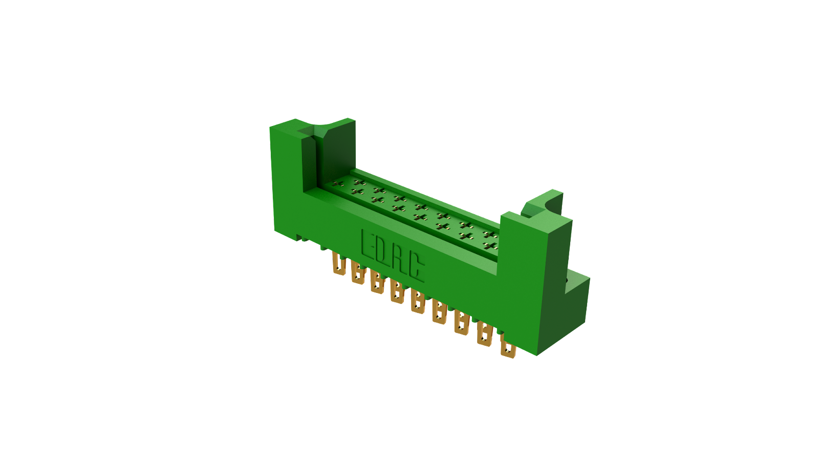
Figure 2: Metal-to-metal card edge connectors use a unique hermaphroditic contact design that floats in the insulator to allow for movement, yielding a high resistance to vibration and mechanical shock.
Header connectors
Header connectors are ubiquitous in all multi-PCB systems in order to connect from board to board. These are used almost universally in sensor systems with myriad off-the-shelf sensor modules leveraging header connectors and will be seen in industrial sensor systems. The header connectors themselves must also be resistant to mechanical stressors such as vibration and shock.
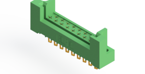
EDAC provides an array of these connectors, including standard box headers, E-Socket and E-Pin headers, high-power headers, and DIN headers. EDAC E-Socket and E-Pin headers are optimized for sensor applications. In this connector, the E-Socket receptacle exhibits a fork-like design that grasps the E-Pin male headers for a highly reliable mate (Figure 3). A high-conductivity copper alloy is used in the pin connection for a good contact spring force that can withstand vibration as well as a low-contact resistance. Up to 50µ'' of gold plating can be used for sufficient protection from fretting corrosion. All of these characteristics allow the connectors to withstand a minimum of 200 mating cycles. Additionally, the E-Socket and E-Pin headers have a wide-operating temperature range from -40oC to 105oC; other high-temperature materials can also be utilized for an extended temperature range.
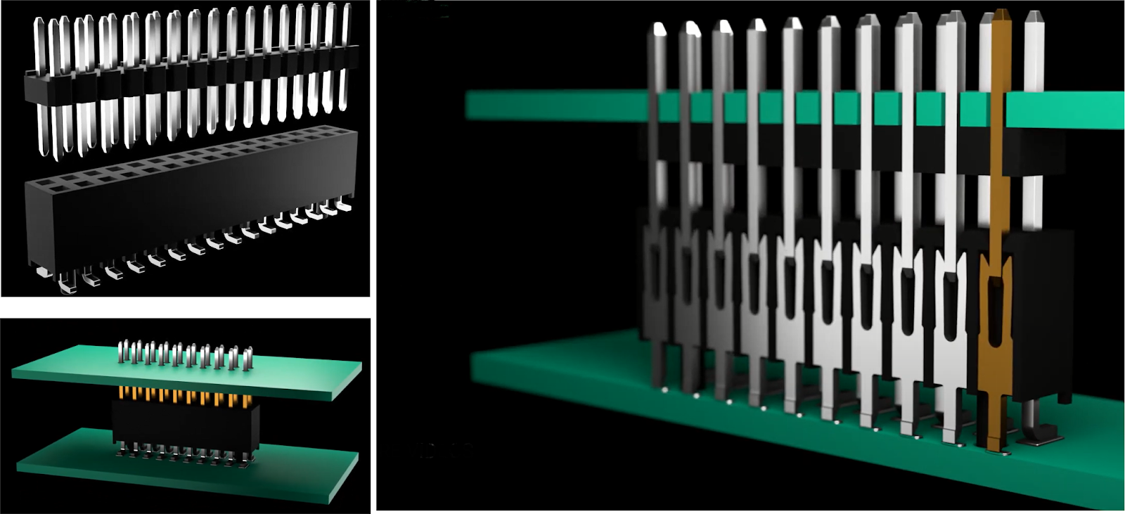
Figure 3: E-Socket and E-Pin headers form a low-resistance mate with a good contact spring force and resistance to vibration.
Inline connectors
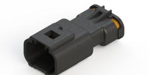
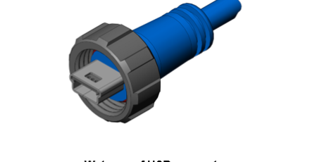
Sensors that are used within a vehicle, such as heavy-duty equipment or the formula-style race cars discussed earlier, will need to be connected to processing systems such as the ECU via wire harnesses. This calls for these connectors to be placed near the engine and free hanging — leaving them at the mercy of the vehicle’s heat generation and vibration. Inline connectors are an option well-suited for this particular application. The connectors have an operating temperature range of -40°C to 105°C. The operating temperature max of 105°C helps the connector endure higher temperatures found around the vehicle’s engine. As shown in Figure 4, an IP67 rating provides absolute protection from dust and complete protection from temporary immersions in water (up to 1 m). EDAC is able to accomplish a waterproof connection with E-seal technology where a proprietary epoxy-sealing process is employed to seal the entire back of the connector rather than the individual pins. This yields a complete seal with a smooth finish and guarantees no water ingress.
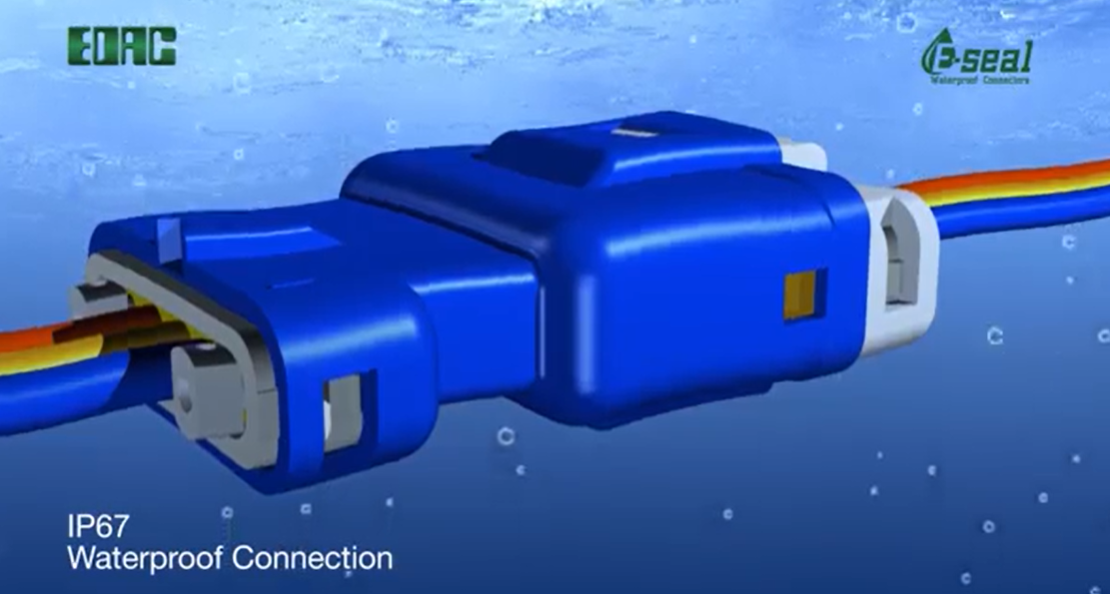
Figure 4: EDAC’s inline connectors have an IP67 rating, which ensures that these connectors can withstand immersion in up to 1 m of water — making them completely resistant to the splashes within a vehicle or industrial environment.
These connectors are designed to either connect directly to a PCB (wire-to-board) or to and from larger sensor systems (wire-to-wire). These cable assemblies will experience a great deal of vibration, so connectors must have a high retention strength. Unlike header and card edge connectors, inline connectors do not have a high pin density and have larger pin sizes (more contact surface area), making them a bit less susceptible to fretting corrosion.
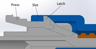
EDAC’s inline connectors use a double-latch technology that provides a higher retention strength (20% more than the single-latch alternative) and therefore a higher vibration resistance. As shown in Figure 5, this technology utilizes plastic latches on the top and bottom of the receptacle connector that slide into the housing until they reach the slots. The slots lock them in place between the male and female inline connectors.
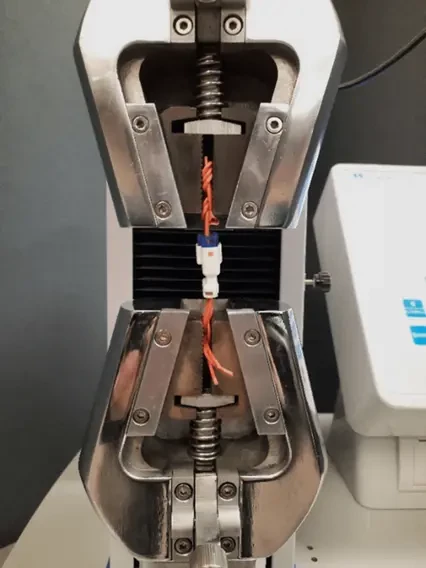
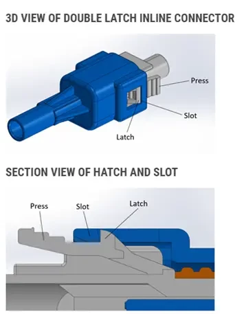
Figure 5: An image of the EDAC inline connector’s double-latch system (left) as well as the retention test setup for the 560 series inline waterproof connectors (right).
EDAC conducted several vibration- and retention-related tests to ensure the connectors could withstand an in-vehicle application. Vibration testing was performed in accordance with MIL-STD-202G 201 where the 560 series inline connectors were attached to three axes for two hours on each axis at 10Hz-55Hz-10Hz with a maximum amplitude of 1.52 mm. During the test, the 560 series inline connector and the low-level contact resistance were below 8mΩ and equal to 8mΩ after the test; the 560 inline series specifies a maximum contact resistance of 15 mΩ, and this falls well below it. During the test, the sample did not fall off, rupture, or damage, and the connector joint did not separate.
The retention force test (Figure 8) clamped both the single-latch male and female double-latch connectors on the tensile testing machine and compared them. The connectors were pulled at a rate of 25 mm/min. The double-latch connector retention force averaged around 10 kilogram-force (kgf), and the single-latch was around 8 kgf.
D-sub and USB connectors
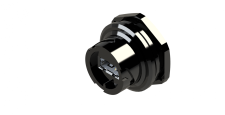
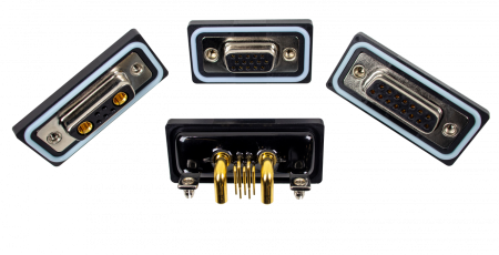
Sensor modules can connect to USB-enabled equipment such as a data logger or computer, while D-sub connectors can be used in data acquisition (DAQ) cards and PLCs to collect sensor data. In sensor applications, these connectors might have to be resistant to mechanical and environmental stresses. EDAC offers IP67-rated D-sub and USB connectors that use the E-seal technology to accomplish a watertight seal (Figure 6).
The standard USB connector has a very poor retention strength and would not be able to maintain a mate under much mechanical strain, let alone constant vibration. EDAC’s IP67-rated USB connectors leverage either a bayonet-style (for Type-A) or threaded (mini) mate for a high-retention, vibration-resistant connection.
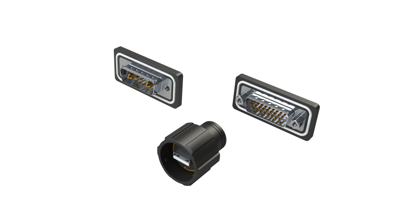
Figure 6: EDAC’s IP67-rated D-sub and USB connectors.
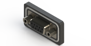
Waterproof D-sub connectors include both standard D-subs with signal-only pins and the Combo D-sub with power or signal pins. The combo design allows for space savings in highly embedded sensor systems with both power and signal connections included in a single connector. As shown in Figure 7, the D-sub connectors feature a two-prong boardlock for retention and grounding to the PCB. Standard screw-locks are used to ensure a reliable mate is formed between connectors.
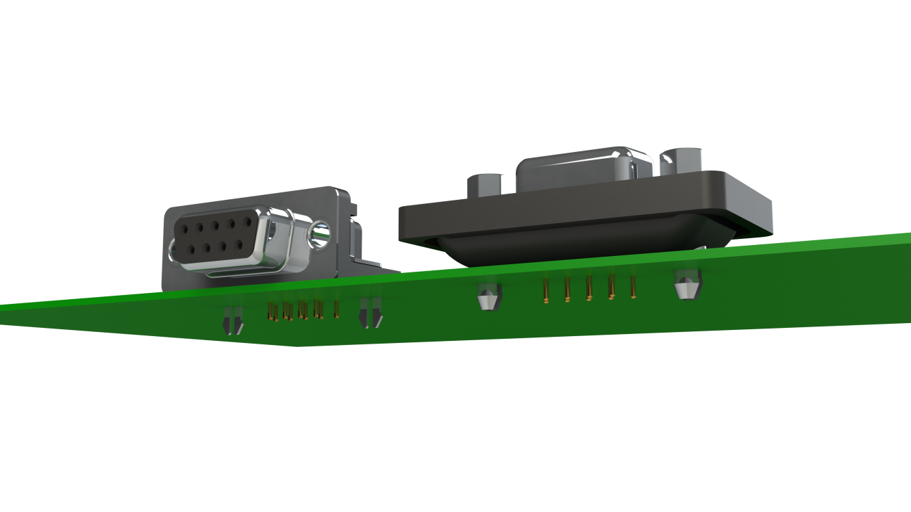
Figure 7: EDAC’s waterproof D-sub connectors feature a two-prong boardlock for exceptional retention to the PCB.
Conclusion
Systems that incorporate sensors are often turning physical phenomena into electrical impulses for measurement and monitoring purposes. This implies that these systems will have to be embedded in what might be considered harsh environments for electronic equipment. The connector heads themselves must be able to withstand potential vibrations, mechanical shock, thermal shock, and moisture ingress. All of these strains come with unique failure mechanisms that will cause the part to fail prematurely.
All parts within the connector, including the housing, strain relief, and pins, will have to take into consideration these failure modes in order to ensure the cable assembly can survive the lifetime of the larger system being monitored. This often means the connector must be IP rated to prevent moisture ingress with construction that accounts for severe mechanical vibrations and shock. EDAC offers a massive array of connectors for sensor applications from board-to-board, wire-to-board, and wire-to-wire configurations. This gives the customer the ability to find the optimal connector for their specific sensor use case.
Relevant Sensor Connectors
Sensor Connectors
Waterproof USB Connectors
Series |
Description |
|---|---|
690W Series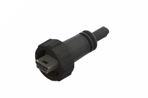
|
Waterproof USB Connectors |
Metal to Metal Card Edge Connectors
Series |
Description |
|---|---|
408 Series%20Connector.png)
|
High Reliability Inter-Lock | Green | Metal to Metal | Receptacle | Closed Card Slot |
415 Series%20Connector.png)
|
High Reliability Inter-Lock | Green | Metal to Metal | Receptacle | High Profile Insulator | Closed Card Slot |
421 Series%20Connector.png)
|
High Reliability Inter-Lock | Green | Metal to Metal | Plug | Mounting Ears |
422 Series%20Connector.png)
|
High Reliability Inter-Lock | Green | Metal to Metal | Plug | No Mounting Ears |
423 Series%20Connector.png)
|
High Reliability Inter-Lock | Green | Metal to Metal | Plug | Mounting Ears with Guide Pins |
424 Series%20Connector.png)
|
High Reliability Inter-Lock | Green | Metal to Metal | Receptacle | Open Card Slot |
438 Series%20Connector.png)
|
High Reliability Inter-Lock | Green | Metal to Metal | Receptacle | High Profile Insulator | Open Card Slot |
Waterproof D-Sub Connectors
Series |
Description |
|---|---|
627W Series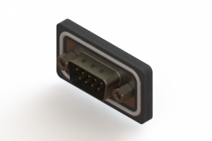
|
D-Sub Connectors | Waterproof | 0.109" (2.77mm) Contact Spacing x 0.112" (2.82mm) Row Spacing | Vertical | Plug |
628W Series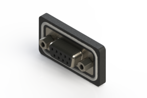
|
D-Sub Connectors | Waterproof | .109"(2.77mm) Contact Spacing x .112"(2.82mm) Row Spacing | Vertical | Receptacle |
629W Series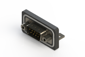
|
D-Sub Connectors | Waterproof | .109"(2.77mm) Contact Spacing x .112"(2.82mm) Row Spacing | Right Angle | Plug |
630W Series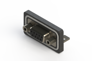
|
D-Sub Connectors | Waterproof | .109"(2.77mm) Contact Spacing x .112"(2.82mm) Row Spacing | Right Angle | Receptacle |
633W Series
|
D-Sub Connectors | Waterproof | High Density | 0.090" (2.29mm) Contact Spacing x 0.078" (1.98mm) Row Spacing | Right Angle | Plug |
634W Series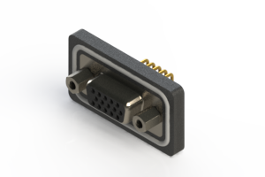
|
D-Sub Connectors | Waterproof | High Density | 0.090" (2.29mm) Contact Spacing x 0.078" (1.98mm) Row Spacing | Right Angle | Receptacle |
637W Series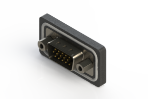
|
D-Sub Connectors | Waterproof | High Density | .090" (2.29mm) Contact Spacing x .078" (1.98mm) Row Spacing | Vertical | Plug |
638W Series
|
D-Sub Connectors | Waterproof | High Density | .090" (2.29mm) Contact Spacing x .078" (1.98mm) Row Spacing | Vertical | Receptacle |
Waterproof Power Combo D-Sub Connectors
Series |
Description |
|---|---|
627WC Series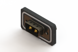
|
Vertical Combo D-Sub Connectors | Waterproof | Plug |
628WC Series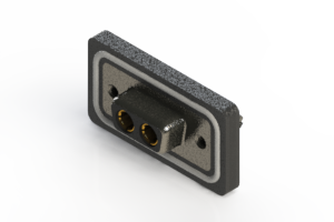
|
Vertical Combo D-Sub Connector | Waterproof | Receptacle |
629WC Series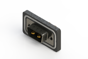
|
Right Angle Combo D-Sub Connectors | Waterproof | Plug |
630WC Series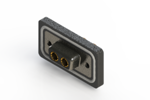
|
Right Angle Combo D-Sub Connectors | Waterproof | Receptacle |
References
- https://partners.wsj.com/emerson/unlocking-performance/how-manufacturers-can-achieve-top-quartile-performance/
- Kong, Zhigang, and Jonathan Swingler. “Combined Effects of Fretting and Pollutant Particles on the Contact Resistance of the Electrical Connectors.” Progress in Natural Science: Materials International, vol. 27, no. 3, 2017, pp. 385–390, https://doi.org/10.1016/j.pnsc.2017.04.018.
- İlknur Baylakoğlu, and Aleksandra Fortier, The detrimental effects of water on electronic devices, e-Prime - Advances in Electrical Engineering, Electronics and Energy, Volume 1, 2021, ISSN 2772-6711, https://doi.org/10.1016/j.prime.2021.100016.
- Liu, Xingyong; Ji, Xiangying; and Zhu, Dexiang, "Electrolytic Corrosion Resistant Plating for Connector Pins", Technical Disclosure Commons, (August 04, 2020), https://www.tdcommons.org/dpubs_series/3493.