Categories
- Card Edge Connectors
- RECTANGULAR CONNECTORS
- D-Sub Connectors
- Machined D-Sub Connectors
- Power Combo D-Sub Connectors
- Parallel Port D-Sub Connectors
- Waterproof D-Sub Connectors
- DB9 Connector
- DB15 Connector
- DB25 Connector
- Vertical PCB D-Sub Connector
- D-Sub Panel Cut-outs
- Cable Wire D-Sub Connector
- PCB D-Sub Connector
- Right-angle PCB D-Sub Connector
- Backshells or Hoods, and Caps for D-Sub Connectors
- D-Sub Connector Housings
- D-Sub Connector Contacts
- Modular & Magnetic Jacks
- USB Connectors
- HDMI Connectors
- INLINE CONNECTORS
- HEADER CONNECTORS
- Spring Loaded Connectors
- Waterproof Connectors
- Cable Assemblies
- Custom Connectors
Search Parts:
Highlights
• Cable assemblies for data and signal processing, and adaptors for intermating connections
• Standard lengths from 1 to 10 meters or 3 to 30 feet
• Breakout cables for multiple terminations
• Adaptors for DVI digital to VGA analog conversion
• USB cables in standard printer/device format (A to B) and alternates (A to A, B to B)
• Mini USB, Mini DIN, RJ45, RJ11, and other computer cables available in bulk
• Virtually any cable manufactured to mate with Edac connectors can be made
EDAC specializes in custom cable assemblies to meet or exceed the needs of your application. We have an extensive array of connectors to utilize in connecting your world. Various cable lengths, shielding, custom colors, customized connectors, wire gauges, jackets, latching mechanisms and custom markings are available.
Cable Assembly Brochure:

Interconnect Solutions Brochure:
The Importance of Understanding the Connector in a Cable Assembly
Cable assemblies are widely used in all conceivable applications, including but not limited to industrial/commercial, transportation, and residential. They offer protection against environmental variables and general wear and tear while also helping to keep wires bundled and orderly. Cables serve as the main “highway” for electronic power and signals, providing “off-ramps” ranging from simple one-way connections to several multi-point interfaces. Though both electronic and mechanical in nature, there are many key considerations when designing with cable assemblies. This article will explore those considerations while highlighting the importance of the connector and its many uses.
Cable assembly key design considerations
Believe it or not, a cable assembly and wire harness are typically used as two separate terms but, in many cases, can be used interchangeably. A wire harness is typically more basic in its construction and performance, and it generally offers less environmental protection and mechanical robustness. A cable assembly might have more features such as shielding, backshells, strain relief, and overmolding. However, both assemblies are subject to five key design considerations.
- Length/termination – The overall length of a cable assembly can make a significant impact on performance. This includes voltage drop, electromagnetic interference (EMI), difficulty in assembly/fabrication, and even introducing challenges in the regulatory domain. For high-speed applications, longer cables can introduce reflections, especially if not properly terminated.
- Size – For space-constrained applications, size and limited-bend radii can greatly impact system density.
- Signal type/performance – The proper configuration and materials must be used for high-speed, high-power, and sensitive analog applications. This may include gold-plated crimps, shielding, and any other special considerations. Twisting differential pairs and shielding/ground wire often help with noise immunity and inductive coupling.
- Usability – The cable assembly may be used frequently, so the designer must consider the needs of service, manufacturing, or the end-user. Things like ease-of-use, accessibility, and misuse prevention can play a large role here.
- Reliability – While often overlooked during design, cable assemblies and interconnections are some of the most common failure points in a system. Ensuring protection against shock and vibration, moisture, high temperatures, and aggressive usage can be critical to a system’s success.
The anatomy of a connector
While length/termination relates more to a cable assembly, the size, signal type/performance, usability, and reliability requirements should feed into the selection of a cable’s connector. Whether it’s wire-to-wire or wire-to-board, a connector has several parts and features that tie directly to the considerations above.
- Connector body – A connector’s body is the main structure of the connector, typically consisting of insulating material that houses the contacts. To allow for better usability, these bodies can often feature latching and/or locking mechanisms while also sometimes including screws and Parallel Economic Models (PEMs) to help with mechanical robustness. Polarizing keys, hardware, or connector body design can make the connector orientation-dependent which helps prevent misuse. The materials used can greatly impact performance depending on the application. For instance, integrated magnetics may be required for high-speed ethernet connections, while thick, insulating walls help meet creepage and clearance requirements for higher-voltage applications.
- Contacts – A contact is typically the mating pin in a connector and interfaces to the wire, either by a tool or, in rare cases, solder. Its power rating and contact finish must be considered for high-power and high-performance applications, while the crimp style plays more into usability and reliability. Some crimps are easier to assemble than others, and having something that is compatible with multiple connector types can make both the design and sourcing process a lot easier.
- Backshells – A backshell may be added to a connector assembly to provide environmental protection and strain relief while also providing grip and surface area during use. Some backshells are metallic and used in grounding/shielding, and others may be insulators. The backshell may come with a band clamp or grommet to improve robustness and reliability for high-cycle count usage and flexing. – Finally, overmolding can help join the connectors, wires/crimps, and backshell into a single piece. This consists of an insulating material such as thermoplastic polyurethane (TPU) or polyvinyl chloride (PVC) and often requires custom injection or insert molding. There are many benefits to overmolding, such as opportunities for branding/colored materials, custom shapes, durable and long-lasting construction, water/shock resistance, and increased strain relief.
In addition to the construction of the connector, it’s important to consider any regulatory requirements in your application, such as UL or IEC approvals/certifications. And let’s not forget the datasheets and drawings that accompany the connector. Sometimes it can take a while to get a clear picture of “pin 1” or a particular pin-out schematic associated with the connector. Having this information clearly indicated in a drawing can greatly increase a designer’s confidence.
Real world applications
Let’s take a look at some of the most common examples of connectors and how they relate to the considerations described above.
- Card edge – A connector designed to mate to the edge of a printed circuit board (PCB), typically for high-performance parallel interconnects between memory devices (like SD cards or graphics cards) and PC/computers. These can be very low-profile connections to increase system density and are becoming even more popular with the extensive use of systems on modules (SOMs) in processing boards.
- Rack and panel – A connector system that bundles many different types of wire for large, mixed-signal equipment connections. These connections may include several sizes of crimps that allow for both power and data interfaces combined into a single connection.
- D-Sub – A highly standardized connector that suits a wide range of electronics ranging from communications ports to power supplies. Examples include RS-232, VGA, SCSI, and a variety of other consumer-based connections like printers and gaming systems. These often come with backshells and screws/PEM nuts and are meant for more rugged environments.
- Mod-jacks – Another popular connector amongst medium- and high-speed communications interconnects. Ethernet (8P8C), data (6P6C), and phone (4P4C) are all common examples of modular jack connectors and often consist of color-coded jackets/shielding and twisted pair wiring for EMI protection.
- Inline – Though many options exist and few are standardized, inline connections are used for more specific connections that provide quick/efficient ways of connecting two wire assemblies together, either internal or external to a system.
- HDMI – A high-performance video and audio connection that is certified/tested to HDMI standards and used for various platforms such as DVD players, TVs, PCs, teleconferencing systems, and other multimedia devices. Note that for HDMI applications, a product is required to certify its HDMI input/output ports to properly label and use HDMI terminology. Most HDMI connections include customized overmolding for labelling, ease of use, and mechanical robustness. Like most high-performance connections, HDMI quality can suffer with longer cable lengths.
- USB – Similar to HDMI, there are many commonly used speeds and form factors of USB ranging from USB 2.0 full speed (data) to USB 3.2 Gen 2 (data, audio, video, bi-directional power/charging). Though the USB organization is looser on USB terminology, incorporating logos and trademarks can still require adoption and certifications during design and product launch. USB-C connections support some of the fastest data rates seen in the industry (up to 40 Gbps) while also supporting a whopping 240W of power delivery (over shorter, full-featured USB-C connections). Though many brands exist, some are higher quality than others based on the materials in their construction (including ferrite beads, shielding, gold-plating, overmolding, etc.).
- Headers – Probably the most common connector for board-mount connections, male and female headers typically consist of standard pin spacing (such as 0.1”) with several rows and a simple rectangular plastic base to help with keyed/locking connections but can also come in denser, higher-pin-count packages. They are highly cost-effective and can support a wide range of mixed-signal and low-medium power applications.
- Spring-loaded – For vibration-sensitive applications, spring-loaded terminations consisting of pogo-pins and magnetics can greatly increase the reliability of a connection. In addition, they make for great low-profile (connector-less) programming and test interfaces with arrays of exposed copper pads and guide holes.
EDAC’s connector portfolio and case study
EDAC offers a broad range of interconnect solutions for a variety of markets such as consumer, telecom, data, industrial, transportation, medical, energy, broadcast, and lighting. The product page showcases many of the standard connectors described above while others help with more special considerations such as watertight and magnetic configurations. In addition, EDAC also assists with custom connector applications in either full custom designs or modifications of pre-existing/standard products. With inventory checks, quick access to 3D models, drawings/datasheets, and an engineering support team on call, a designer can incorporate many types of high-quality interconnections from the same brand/vendor in a design, helping to boost sourcing efficiency from both an R&D and manufacturing perspective.
It’s ideal to work with an interconnect manufacturer that both offers an extensive portfolio and helps customers with unique applications. Let’s explore a few case studies in which EDAC worked with customers to leverage some of these off-the-shelf connectors and customize their cable assemblies to best meet their needs.
Case study 1: Waterproof cable assembly
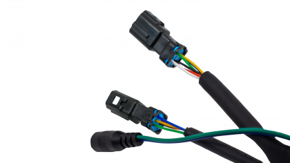
The overall objective of this case study was to design a cost-effective cabling system that can scale from a single monitor to a daisy chain monitor system while meeting regulatory requirements. This included the design of a low-cost waterproof cabling system that could be used effectively in large-sized LED/LCD monitors in outdoor stadiums without impacting the power/signal transmission quality. One of the main challenges was meeting the regulatory requirements with a daisy-chained system, but, overall, the solution provided an optimized, waterproof connector that improved the electromagnetic interface using twisted pair cables and simplifying the sealing process from IP67 to IP54.
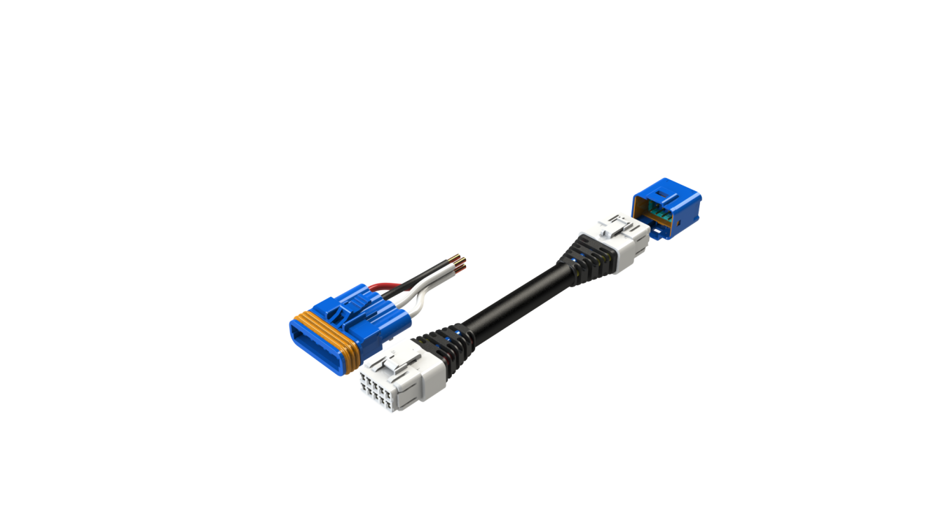 Figure 1 - Waterproof Cable Assembly
Case study 2: Polarized D-Sub and backshell
The goal for this study was to design a shell and key base to mate before the D-Sub cable is connected to the board. The project required minimal tooling, ease-of-use design, and manufacturing scalability. The idea here was to polarize the D-Sub cable assembly shell to prevent incorrect mating on the PCB board. One of the main challenges entailed the mating of the shell and key base before the D-Sub cable connection as it restricted tooling and ease-of-use. However, the end solution incorporated interchangeable inserts in the mold for different polarized positions identified by letters and numbers, and also an increased height of the PCB key base adapter on the board by 10mm to mate the D-Sub shell before the connector.
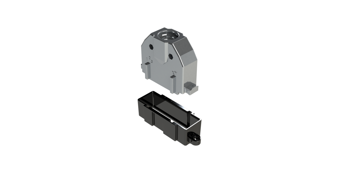
Figure 2 - Polarized D-Sub and Backshell
Case study 3: Digital-to-analog multipoint cable assembly
See the picture below showing an application in which various cable lengths, shielding, colors, connectors, wire gauges, jackets, latching mechanisms, and custom markings are showcased in a single assembly.
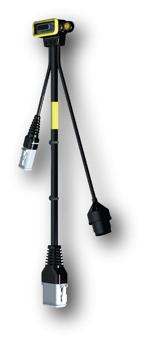
Figure 3 - Digital-To-Analog Multipoint Cable Assembly
In general, EDAC offers cables that include standard lengths from 1-10 meters, breakout cables for multiple terminations, adapters for DVI-digital-to-VGA-analog conversion, USB cables in standard printer/device format (A to B) and alternates (A to A, B to B), mini-USB, mini-DIN, RJ45, RJ11, and other computer cables.
It’s important to consider both the construction of the connector and how it’s incorporated into a cable assembly. The designer must study the application's demands and properly select materials based on cable length, size/space constraints, signal types and performance requirements, usability, and reliability. Not only does EDAC offer many connectors commonly found in the industry while also offering custom overmold and connector solutions, but it will also help guide a designer through the cable assembly design process. It’s important to partner with a vendor like EDAC that can provide a variety of options, helping the designer optimize size, performance, cost, and create a long-lasting, easy-to-use interconnection that has been optimized to meet or exceed design requirements.
Connect with us… Experience makes the difference.
RESOURCES