Products
- Card Edge Connectors
- RECTANGULAR CONNECTORS
- D-Sub Connectors
- Machined D-Sub Connectors
- Power Combo D-Sub Connectors
- Parallel Port D-Sub Connectors
- Waterproof D-Sub Connectors
- DB9 Connector
- DB15 Connector
- DB25 Connector
- Vertical PCB D-Sub Connector
- D-Sub Panel Cut-outs
- Cable Wire D-Sub Connector
- PCB D-Sub Connector
- Right-angle PCB D-Sub Connector
- Backshells or Hoods, and Caps for D-Sub Connectors
- D-Sub Connector Housings
- D-Sub Connector Contacts
- Modular & Magnetic Jacks
- USB Connectors
- HDMI Connectors
- INLINE CONNECTORS
- HEADER CONNECTORS
- Spring Loaded Connectors
- Waterproof Connectors
- Cable Assemblies
- Custom Connectors
The Need for Designing and Manufacturing Small Electrical Connectors to Fit Smaller PCB Footprints
In today’s world, there’s a constant need for electronics to get faster, cheaper, and smaller. It follows Moore’s law of transistors: The speed and capabilities of computing doubles every two years, primarily due to the increasing density of silicon chips. This expectation is similar at a systems level as well. Sensing, imaging, motion control, communication, and power management are all systems-level aspects that contain interconnections between modules, circuit boards, and power sources. In addition to processing, these systems-level interconnections must also become denser and more compact to lower the footprint of an overall system.
EDAC offers many options in terms of interconnect solutions, including card edge, rack and panel, D-Sub, Modular Jack, USB, HDMI, inline, header, spring-loaded, waterproof, and custom connectors along with assembling the connectors into cable assemblies. One of its newer products (140 series) aims to provide low-profile, wire-to-board inline connections. This article will explore the newer 140 series and how it satisfies the need for smaller PCB footprints and interconnections, while also providing a refresher on what to look for when designing system and board-level interconnections.
Design considerations for systems-level interconnections
Here’s a quick rundown of the typical considerations for selecting connectors in a design:
- Size – For space-constrained applications, a designer must really evaluate the overall system footprint and determine what best “fits” the interconnections in terms of connector entry, location and height restrictions on a PCB, and any other dimensional constraints.
- Ease of use – For applications requiring service, constant use, or streamlined assembly, the interconnection should be a quick and easy process to minimize time on the production floor while also reducing the chance for error during integration.
- Signal performance – All applications are different in terms of performance requirements, but for interconnections the main considerations are typically speed, environmental sensitivities like EMC/EMI or ambient temperature, current ratings (don’t forget to de-rate your connections!), and any special regulatory requirements.
- Sourcing – Given the current sourcing climate and world-wide shortages of electronic components, identifying brands and series of connections that are well-established and have a global presence typically helps with strategic sourcing and minimizing impacts to production and R&D efforts. Keep in mind the lifecycle of a connector and also look for ways to second-source certain parts in a design.
- Brand or series re-use – Sometimes picking a very specific connector or brand for a particular function can add a lot of unnecessary documentation to a design. It’s usually best to pick a brand or series and utilize as much of that series as possible. Standardizing connector brands and series in a PCB design helps minimize tooling requirements for assembly and associated cabling, simplifies R&D parts stock and design files by leveraging similar connectors across multiple designs, and builds familiarity and trust in a brand over time.
- Robustness and reliability – For mission-critical applications or designs requiring a certain level of reliability (in industries such as medical, aerospace, or defense), the system interconnections can be high-risk for failing across a number of conditions. Certain features of connectors can help mitigate these risks, such as keyed and locking connections, and things that minimize electrical and mechanical stress such as high voltage, vibration, and extreme temperatures.
- Vendor support – Most designers rely quite a bit on good documentation/drawings from the vendor that are easy to interpret, as well as accompanying 3D models and a website that is easy to navigate for associated parts. Additionally, quick and thorough follow-up with application engineering support can be critical to ensuring a design’s success.
Designing for compact systems
Though most of these considerations drive the selection of interconnects, size is one of the leading factors in today’s climate and is continuously progressing, though trying to keep up with silicon miniaturization. Higher processor I/O count may result in more systems-based interconnections and peripherals. As systems continue to get denser and more compact, the overall size of the connections can become a balancing act. The designer must weigh many things such as:
- Pin spacing and meeting creepage/clearance rules
- Insulation material
- Connector de-rating for higher current applications
- Avoiding cross-talk across connector pins
- Considering impedance in high-speed systems
- Surface mount vs. through-hole (mechanical strength and reliability)
- General mechanical constraints (such as board stacks and nearby components)
- Cable management and entry paths, bend radius, and stress relief
- Overall usability, such as mating force and accessibility
Though an application’s requirements can vary widely, designing for high-density systems typically requires close attention during design in both electrical and mechanical domains. Trading files back and forth during development, considering systems-level assembly during manufacturing and usability during service or general use, meeting regulatory standards, and designing with enough margin (tolerance stack-up, de-rating maximum continuous pin currents in higher pin-count connectors, EMI protection, and following best practices during PCB layout) all help optimize a system’s density in terms of interconnections. Additionally, higher-quality CAD software with expanded 3D-design features and visualization helps reduce the chance for error at each iteration of a compact design.
Given these design considerations for space-constrained applications, let’s look at some of the connectors in EDAC’s portfolio.
EDAC’s inline connector solutions featuring the 140 series
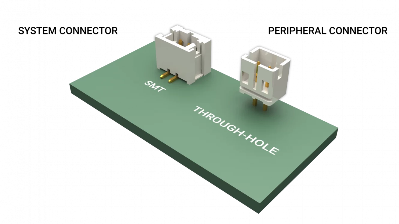
EDAC’s 140 series of inline PCB connectors is designed for high density while also maintaining a wire gauge range (30-24 AWG) and current carrying capacity (up to 2A with 10mOhm resistance per contact) found in most mixed signal/power interconnections. There are two board-mount options that are offered in this series: systems-level SMT mount connectors and peripheral-based through-hole connectors (see Figure 1), each with 2-16 positions available providing a wide range of connections and the capability for a designer to incorporate several different pinouts in a design (to help simplify systems interconnections and tooling). The surface-mount variation provides support for densely routed PCBs, while the through-hole connections provide a sturdy, mechanically robust solution for higher-reliability applications.
Figure 1. Series 140 SMT and Through-Hole Connectors
With 2.0mm (0.079”) fine pitch connections, top- and side-entry options, and an audible click-secure latch, the 140 series supports high-reliability applications with limited space/volume and specific cable routing/interfacing requirements. This series is primarily meant for PC board thicknesses ranging from 0.047” (1.2mm) to 0.062” (1.6mm) and consists of low-profile insulator bodies (0.185” (4.7mm) width and 0.240” (6.10mm) height). Additionally, brass contact material and tin plating, along with a low contact resistance (10mOhms maximum), make for good signal performance, while the connector’s insulation material and resistance meet UL standards. See Figure 2 for a full electrical specification table on the 140 series.
140 Series Inline Connector Specifications
|
Insulator Material |
PA66, UL94V-0, Natural Color |
|
|
Contact Material |
Brass (For Male Header) |
Phosphor Bronze (For Female Contact) |
|
Contact Plating |
Tin Plating (For Male Header) |
Tin Plating, Copper Underplating (For Female Contact) |
|
Current Rating |
2 amps |
|
|
Voltage Rating |
100 V |
|
|
Contact Resistance |
Initial: 10 milliohms maximum |
|
|
Dielectric Withstanding Voltage |
800 V AC rms |
|
|
Insulation Resistance |
1000 megaohms minimum |
|
|
Operating Temperature |
-40C to +105C |
|
|
Applicable Wire |
AWG #30~#24 |
|
Figure 2. Series 140 Electrical Specification
Overall, the 140 series of connectors supports many applications that require compact interconnections of all types of mixed signals. Some examples of this are:
- Medical equipment
- Testing/analyzing equipment
- Wearable technologies
- Automatic doors
- Drones
- Lighting applications
- Consumer
- Sensor technologies
- Industrial
- Process control
- Robotics
And in a world where designing for second-source footprints has become commonplace, these 140 series connectors are compatible as drop-in replacements with many familiar, industry-leading connectors.
In addition to the 140 series, EDAC offers many other inline connectors that support waterproof applications, such as the 560, 565, 566, 567, 568, 570, and 572 series. And if these inline connectors still don’t meet an application’s requirements, EDAC also offers custom solutions as well. But let’s take a quick look at some other options from EDAC that provide some familiar, heavily used connector types as well as some non-standard, high-reliability solutions.
USB and spring-loaded connectors from EDAC
EDAC’s connector portfolio includes many different types of connectors that meet industry standards but contain features that add higher reliability and performance. USB is one of those connection types that is heavily used across all industries, but not all connectors are the same and it’s important to select a connector that will stand the test of time. EDAC’s standard USB options (see Figure 3) range from A, B, and C in vertical or right-angle orientations, and combine data and power in a space-efficient package with reliable PCB-mount and inline cable connections. They feature up to 10 Gbps communication speeds (for USB type C 3.1), industry-standard plug and play technology, compatibility with hot-plugging, asynchronous and isochronous data-transfer methods, and a variety of versions consisting of stacked connectors, different plating options and material, and connector types.
Figure 3. EDAC’s USB Portfolio
In addition to industry-standard connectors like HDMI, D-SUB, and Mod Jack solutions, EDAC also offers non-standard connections meant for high-reliability applications. One example is the magnetic spring-loaded 685 and 686 connector series (Figure 4), which includes pogo pin contacts and magnets to help increase the mechanical and environmental reliability of the connection while providing polarization as well. These reliability improvements include:
- Stable current flow during vibration and moving parts
- High number of mating cycles (up to 30,000) for demanding test environments
- “Tear away” design preventing damage caused by unintended disconnects
- Upgrade to pre-existing pogo-pin connections held together by mechanical latching
Figure 4. EDAC 686 Series of Magnetic Spring-Loaded Connectors
Low-resistance and high-current ratings (2A per contact), along with a compact, low-profile footprint, make this connection suitable for a variety of applications consisting of lower-voltage (5V and 12V) mixed signal and power in space-conscious systems.
EDAC can help
It’s important to carefully consider the needs of an application before choosing an interconnection, especially if the design requirements drive interconnections to be compact. Compact designs typically demand higher attention to detail in terms of electrical and mechanical features, such as contact ratings, mating connections and their entries, combining signal and power into the same connections, and more focus on designing for manufacturing, service, and reliability. The 140 series of inline connectors from EDAC meets a broad range of applications and satisfies many different mixed-signal applications, while providing a good balance in terms of pin density/spacing, signal performance, electrical and mechanical reliability, and overall usability. EDACs portfolio of high-density and high-reliability connectors can help designers build long-lasting, easy-to-use products that maintain a low-profile footprint across many industries like industrial, consumer, robots, processor control, and medical. Additionally, EDAC’s engineering department consists of more than 55 years’ of experience and works directly with customers to form partnerships and ensure long-term success.
Connect with us… Experience makes the difference.
Resources
140 Series Inline Connector Informative Video by EDAC
Go Back


