


Products
- Card Edge Connectors
- RECTANGULAR CONNECTORS
- D-Sub Connectors
- Machined D-Sub Connectors
- Power Combo D-Sub Connectors
- Parallel Port D-Sub Connectors
- Waterproof D-Sub Connectors
- DB9 Connector
- DB15 Connector
- DB25 Connector
- Vertical PCB D-Sub Connector
- D-Sub Panel Cut-outs
- Cable Wire D-Sub Connector
- PCB D-Sub Connector
- Right-angle PCB D-Sub Connector
- Backshells or Hoods, and Caps for D-Sub Connectors
- D-Sub Connector Housings
- D-Sub Connector Contacts
- Modular & Magnetic Jacks
- USB Connectors
- HDMI Connectors
- INLINE CONNECTORS
- HEADER CONNECTORS
- Spring Loaded Connectors
- Waterproof Connectors
- Cable Assemblies
- Custom Connectors
Engineering Considerations for Connectors in Energy Applications
In the quest to limit the global consumption of fossil fuels such as oil, coal, and natural gas, renewable energy technologies including hydropower, wind, solar, biomass, and geothermal coupled with energy storage systems (ESS) form the backbone of a more environmentally conscious electricity generation. Early this year, the U.S. electricity siphoned from renewable resources surpassed both coal and nuclear power generation [1]. The growing installation of these systems faces serious connector and cabling challenges ― a 100 MW solar farm may have over 700 km of cable with over 100,000 connectors [2]. Nearly all renewable energy systems will interact with saltwater, causing these systems to either fail from water damage or potentially corrode rapidly without adequate protection. The harsh environments presented by electronic systems within applications require sufficiently ruggedized connectors. This article discusses some renewable systems and the engineering considerations for connectors used within renewable energy applications.
Connectors in land and floating photovoltaic (PV) systems
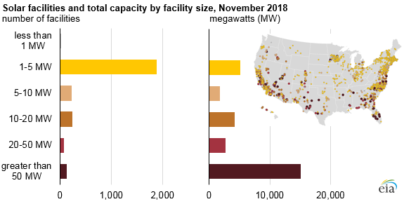
Solar power is the third largest source of renewable energy in the U.S., surpassed only by wind and hydropower. Large PV parks are being installed globally, covering around 6 to 9 acres of land and yielding around 1 megawatt (MWac) of power. Most of the PV power plants in the U.S. are 5 MW or less and are scattered throughout the entire country (Figure 1).

Figure 1: Solar facilities in the U.S. and total capacity by facility size. Source: U.S. Energy Information Administration
Solar parks can go much larger. Bhadla Solar Park in the Thar Desert of Rajasthan, India, for example, covers 14,000 acres and outputs a whopping 2,245 MWac. The Noor Abu Dhabi Solar Power Plant generates 1.177 GW and provides power to over 90,000 homes. This plant uses a waterless robot cleaning system comprising nearly 1,500 dry cleaning robots to clean all the 3.3 million solar panels daily.
Most solar panels are directly compatible with the MC4 connector, allowing for strings of panels to be connected to scale-up power. IEC 62548, NEC, and UL6703 standards for PV system design will all generally require that the PV connectors should be of the same type and brand to eliminate the risk of operator shock from cross-mating. Battery banks are created by connecting battery modules together in a rack. These can also be scaled up by connecting multiple racks together. The modules themselves typically come with an RS485 communications interface for direct connection with a PC, while others may also include RS232 and CAN interfaces to expand the type of communication protocol used. All these communications interfaces can use a D-subminiature (D-sub) connector or an RJ45 ethernet connector. Commercial inverters similarly use RS232, RS485, and USB for on-site monitoring and control as well as ethernet and sometimes built-in cellular for remote monitoring/control. While the battery banks and inverters can reside within a temperature-controlled room, outdoor or portable installations still exist and may require ruggedization.
Connectors in land and offshore wind power
Wind turbines contribute to over 10% of the power generated in the U.S., which has increased from 6 billion kilowatt-hours (kWh) in 2000 to about 380 billion kWh in 2021. Wind power is the leading non-hydro renewable globally where onshore technologies are already matured, and installation sites continue to grow. Offshore wind power is following suit with over 21,000 MW of offshore wind power newly installed in the year 2021 alone [3].
The wind turbine structure includes the foundation, tower, rotor and hub, nacelle, and generator (Figure 2). For offshore wind turbines, different foundations are built ― some in the seabed and others that float ― that support the structure of the wind turbine.
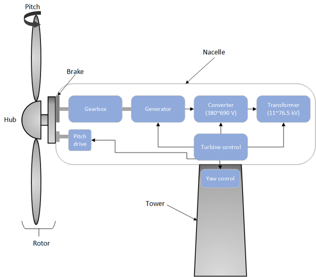
Figure 2: Basic construction of a wind turbine.
Within the nacelle, a generator converts the wind’s kinetic energy from the spinning rotor blades and main shaft into electricity with a generator. From here, the converter will take the input AC power at a given frequency from the generator and output a different regulated voltage (390 to 690 V) at a different frequency. Finally, the transformer is used to step-up the voltage (11 up to 76.5 kV) to connect to the national grid for long-distance transmission. Both the converter and the transformer can be installed within the tower or the nacelle. Interspersed turbines are laid out such that each can receive optimal wind forces for electrical conversion and connected underground and grouted to an onshore or offshore substation.
Electrical connectors used within turbines are quite varied, including high-voltage connectors in the power conversion system meant to carry power from the generator to the converter and transformer. In offshore applications, subsea transformers can be utilized (up to 50 kV) with connectors that enable a wet mate where it can be submerged in water without affecting the electrical connection. There are also connections to and from sensor systems (bearing temperature sensor, pressure sensor) and the nacelle’s control unit for control of turbine pitch (blade angle) and yaw (direction of nacelle) for optimized use of wind energy. Control units are often placed in both the nacelle and at the base of the tower, and fiber optic cables are run to and from each unit for fast, reliable communications. Other wind turbines also include a control unit within the hub that communicates with the control unit within the nacelle with serial communications. Control interfaces used within the converter rack for regulating power according to the PLC include various industrial ethernet or field bus interfaces such as EtherCAT, PROFINET IO, PROFIBUS-DP, CANopen, Modbus, ControlNet, InterBus-S, DeviceNet, as well as standard ethernet for monitoring via PC.
Connectors in hydroelectric power
Hydropower is siphoned from the movement of water. A pipe, or penstock, is laid out on a dam wall near a large body of water (e.g., a reservoir) so that gravity will cause the water to naturally flow down the pipe. The movement of water from the reservoir through the pipe spins an optimally positioned turbine which, in turn, turns a generator and converted electricity is stepped up via a transformer to power the local grid. As shown in Figure 3, control systems are used in all these systems to track each part in the system. The controller for the turbine, called the “governor,” is meant to modulate the flow of water in the penstock by controlling the actuator that opens and closes the guide vanes ― screens that block or open the flow of water from the reservoir into the penstock. Other monitor and control systems include the condition monitoring of hydro turbines, pumps, generators (excitation control systems), and other rotating equipment that might require scheduled maintenance during the lifetime of the plant (these plants can last for a century). Proportional integral (PI) or proportional integral derivative (PID) tuning is usually accomplished with programmable logic controllers (PLCs). Protocols for these SCADA systems are generally standard for industrial communications (e.g., Modbus, ControlNet, DeviceNet).
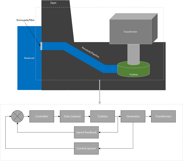
Figure 3: Block diagram of a hydropower plant.
Environmental requirements for energy applications
Solar installations must endure the rising volatility in climatic conditions, including harsher UV radiation and moisture intrusion from wind, rain, snow, and hail. Floating PV systems include Sungrow Power Supply’s solar farm in Huainan, China, with 160,000 panes producing 200 MW of power (Figure 4) and NJR Clean Energy Ventures’ farm in New Jersey. All floating farms are installed on lakes instead of the sea as waves might damage solar panels. However, research for ocean-based solar farms is already underway as large installations would not take up habitable land that might otherwise be used for agriculture or livestock.
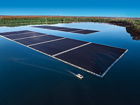
Figure 4: A floating solar farm in New Jersey is the U.S.’ largest floating solar array with over 16,500 panels, producing 8.9 MW. Source: New Jersey Resources
Enclosures and electrical connectors used for the control systems, generator, and transformer within a hydropower plant also will require protection from water ingress as these systems are in direct contact with flowing water and will be in a high-humidity environment. Multi-contact ingress protection - (IP) rated connectors and standard connectors such as D-Sub, USB, and ruggedized to submersion in water might be critical for both onshore and offshore wind systems as well as hydropower systems to ensure electrical connections can be maintained over the lifetime of the system.
Mechanical requirements for energy applications
Generally, the primary issue with medium- to large-scale solar farms is upfront cost with the number of solar panels, frames, and connector and cable runs necessary. The infrastructure grows rapidly. Connectors must be straightforward to install with interoperability.
Within the wind turbine, connectors and cables are subjected to high vibration. Another stressor is the sheer length of the cables running up and down the tower; cables need to be supported with some type of strain relief to prevent leads from being pulled out from the electronics within the nacelle (e.g., generator, converter, transformer, PLC). Compression terminal kits are often necessary for making vibration-proof splices when wiring the turbine [4]. These connectors and cables must be able to operate in harsh ambient conditions where salt, sand, dust, and 100% relative humidity stress is ever-present. The converters and transformers themselves are often rated to perform in these environments with pre-specified IP and UL ratings.
Electrical requirements for energy applications
Electromagnetic interference (EMI) can emanate from wind turbines, causing interference with communications systems, medical devices, and even with avionics from passing aircraft, interfering with critical systems as navigation. The fast-switching power supplies within the nacelle of a wind turbine and PV system can generate noise, as will wind turbine blades causing a dynamic magnetic field. It is important that connected wires and cables do not become a source of conductor emissions as these EMI can propagate through conductive paths and transfer to other sensitive systems. To avoid the potentially catastrophic consequences of EMI, it is important to do the following:
- Ensure that connections to and from any power electronics system have EMI shielding or metal shells/covers
- Ground the shield in both the connector and cable to chassis ground
- Properly terminate cables with the connector
- Use shielded cables over unshielded cables
Inline connectors for energy applications
EDAC offers a large portfolio of wire-to-wire, wire-to-board, and board-to-board solutions that are specifically designed to function when faced with water or dust ingress, constant vibration and mechanical shock, and extreme temperatures.
In wind turbines and hydroelectric dams, wire harnessing is needed to connect between sensors that monitor the health of rotating parts and the controller. The EDAC inline connectors are ideal in environments that expose electrical connections to a high degree of mechanical and environmental stress (e.g., in-vehicle wire harnessing for heavy-duty equipment). Select connectors have an IP67 rating that ensures the mated connection is entirely dust-tight and can withstand temporary immersions in water up to 1 meter. The IP67 rating is achieved in several EDAC connectors through their E-seal technology that uses an epoxy-sealing process to seal the entire back of the connector rather than the individual pins, limiting the risk of continuity issues from epoxy wicking the leads. Water and dust ingress protection is critical in onshore and offshore renewables as well as hydroelectric power as these systems may be constantly exposed to wetness and sandy environments (e.g., desert), so IP ratings are a very useful tool in checking viability of the connector system within the application.
Inline connectors with the double-latch system are almost immune to accidental disconnection or vibration strain. EDAC performed vibration testing according to MIL-STD-202G 201 (three axes, two hours on each axis, at 10Hz-55Hz-10Hz, max amplitude of 1.52 mm), the connectors maintained a low level of contact resistance (8mΩ) and the sample did not fall off, rupture, or damage, and the connector joint did not separate. A retention test was also performed (Figure 5) where the sample was pulled at a rate of 25 mm/min: the single-latch retention force was 8 kilogram-force (kgf) while the double-latch averaged around 10 kgf. The high-retention force ensures that the connectors will not be accidentally disconnected in the event of a tug or high vibration.
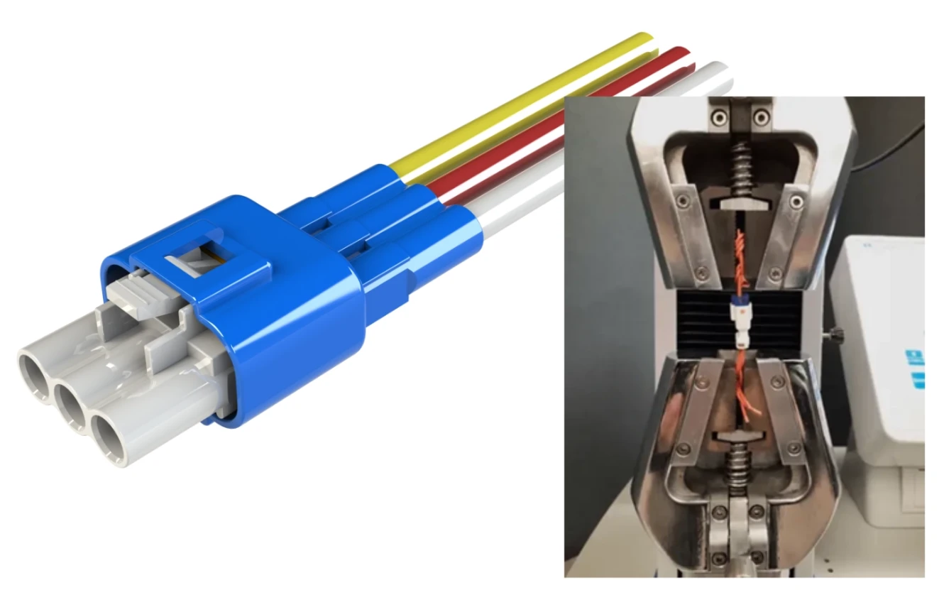
Figure 5: EDAC’s inline connectors can come with an IP67 rating as well as resistance to vibration and accidental disconnects — making them completely resistant to the splashes or high-humidity environments found in onshore and offshore renewable energy applications.
USB connector for energy applications
USB connectors are frequently leveraged in portable solar panels with USB charging capabilities (Figure 6) or for connecting/configuring the charge controller in smaller solar installations. Conventional USB connectors will experience a disconnect when encountering vibrations and cable tugs and therefore require a mate that is difficult to reverse. USB cables used in portable solar equipment will also require a degree of water and dustproofing to prevent ingress and water damage. Contaminants such as dust can act as an insulating barrier, blocking the current flow from connector pin to the other in a mate causing poor contact reliability. Humidity, moisture, or contaminants that contain electrolytes can create corrosion that will interrupt electrical contact and cause signal attenuation.
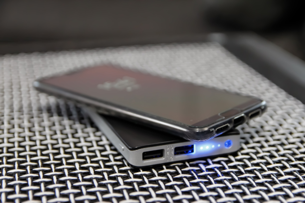
Figure 6: USB connectors can be used for direct connection with solar for USB charging, to configure the charge controller, or even inverters for in-vehicle power.
EDAC offers a range of waterproof USB connectors well-suited for these environments, allowing manufacturers to integrate USB capability within their equipment without sacrificing performance. These connectors are also IP67 rated with either bayonet-style (for Type-A) or threaded (mini) mate for a connection that is resistant to vibration and accidental disconnects (Figure 7). The waterproofing and dustproofing ensures mated connections (or unmated connections with dust caps) will perform during the lifetime of the system.
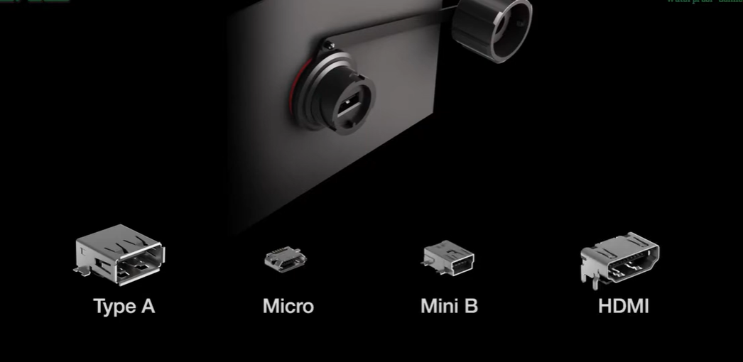
Figure 7: EDAC offers a line of waterproof, IP67-rated USB connectors in USB type A, C, micro, and mini-B, and HDMI connectors.
D-sub connectors for energy applications
D-sub connectors are used for serial and parallel communications in data acquisition (DAQ) cards and PLCs to collect sensor data and control equipment such as that in the nacelle control unit for wind turbines or the governor in hydroelectric power. These connectors are crucial for control systems in wind and hydroelectric energy; however, they may also require ruggedization due to their high-stress environment. As shown in Figure 8, EDAC has a massive offering of D-sub connectors in multiple sizes, pin counts, signal configurations, and levels of ruggedization as follows:
- Sizes: DB9 (or DE9), DB15, DB25
- Pin counts:9, 15, 25, 26, 37, 44, 50, 62, and 78
- Connector configurations: signal only, power only, and power + signal
- Signal contacts: stamped (3 A current rating), machined (5 A current rating)
- Power contacts (up to 40 A current rating)
- Ruggedizations:
- Waterproof (IP67 rating): epoxy seal at rear and O-ring seal to the panel
- Metal shells for EMI and RFI shielding
- Gold flash or gold plating (up to 30 µ”)
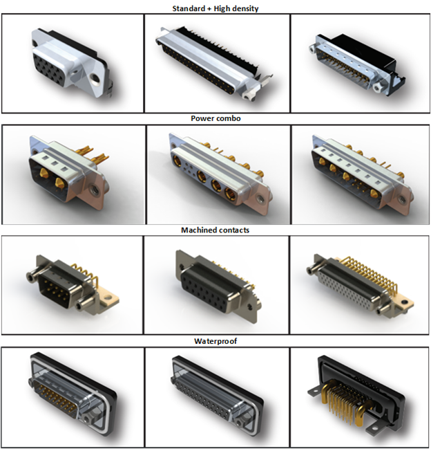
Figure 8: The variety of D-sub connectors offered through EDAC.
Renewable energy applications may require power and signal connections to save space and minimize cable runs with highly embedded sensor systems. The IP67-rated waterproof D-Sub connectors come with 9-, 15-, 25-, 26-, and 44-pin versions with a range of mounting options. These connectors are completely epoxy sealed, the leads are potted in a mold, and a silicone O-ring is added for the waterproof rating.
For D-Sub connectors mounted directly onto a PCB, EDAC offers a two-prong boardlock for retention and grounding. Standard screw locks are also leveraged between connectors to ensure a reliable mate is formed. Both features ensure the connector is able to withstand the vibrations often found in renewable energy systems.
Header and Card-Edge Connectors for energy applications
Pin/socket and power header connectors for energy applications
Wire-to-board and board-to-board connectors such as header and card-edge connectors are used almost universally in any electronic system. These are invariably applied within renewable energy circuits (e.g., power supplies, control circuitry, wireless monitoring, BMS, charge controllers). For PCBs, the enclosure is relied upon for ruggedization from contaminants such as moisture and dust. In some cases, the enclosure may be temperature- and humidity-controlled to prevent damage from thermal shock or high-moisture environments. In other words, the qualities that characterize connectors that mount directly to a board diverge from wire-to-wire connectors. These connectors will require a reliable mate that can withstand vibration and, in some cases, have a high number of mating cycles. Connector factors that optimize this performance generally boil down to the connector pins (e.g., plating, pin construction).
EDAC offers standard box headers as well as more rugged pin and socket header connectors. Box headers are often used with ribbon cable for wire-to-board connections with an enclosure. EDACs E-pin male headers and E-socket receptacles are capable of a minimum of 200 mating cycles. As shown in Figure 9, the E-socket receptacles feature a fork-like shape and utilize a high-conductivity copper alloy that grasps onto E-pin male headers with a high-contact spring force, high retention strength, and a low-contact resistance of 10 mΩ.
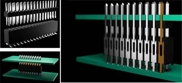
Figure 9: E-socket and E-pin headers will mate to form a vibration resistant board-to-board connection.
High-power header connectors are also available that offer up to 20 A of rated current (Figure 10). These connectors have integrated grounded plane contacts that are offset from the power connectors with a 4-mm pitch between contacts to minimize the risk of arcing and increase the safety of the power connection.
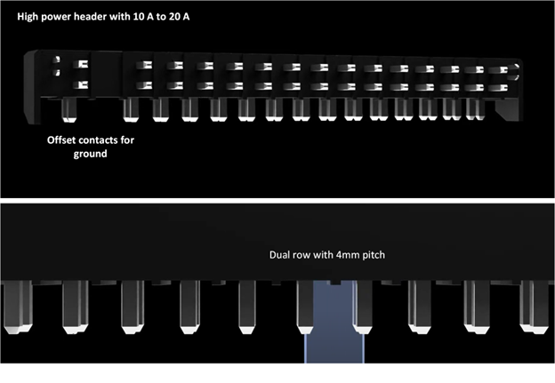 Figure 10: Power header connectors with dual-row configuration and rated up to 20 A.
High-speed and metal-to-metal card-edge connectors for energy applications
Card-edge connectors are also used to extend the capability of embedded computers with expandable card-edge-connected slots. A variety of high-speed backplanes with PCI, PCIe, SAS, or SATA slots can be used with DAQ cards and I/O modules to collect sensor data, perform the processing necessary to analyze incoming data, and control the actuators in a renewable energy system. EDAC’s offerings of card-edge connectors contain nearly half a million products with a variety of contact spacings, terminations, plating thicknesses, and mounting styles. High-speed card-edge solutions are available with PCIe 3.0 or SAS 3.0 compliance (Figure 11).
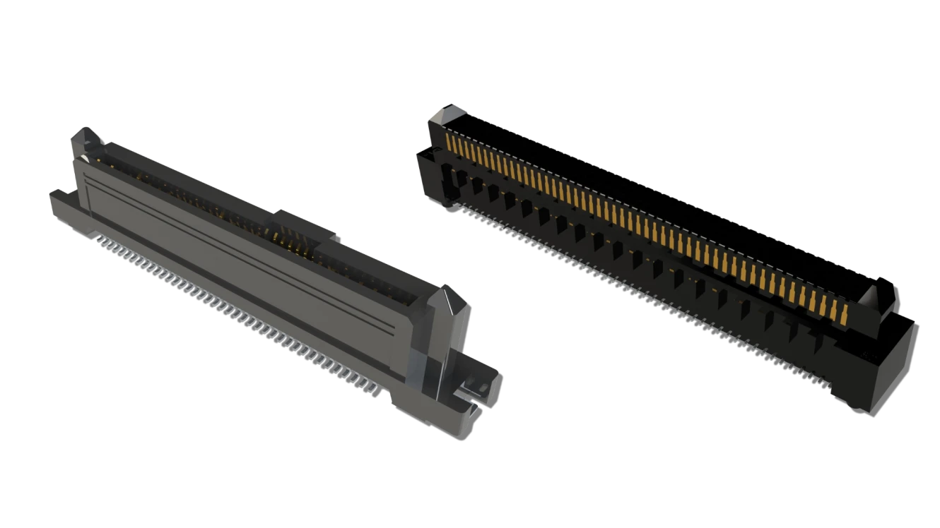
Figure 11: High-speed card-edge connectors are available that offer a data rate up to 21 Gbps with SAS 3.0 and PCIe 3.0 compliance.
The high-reliability card-edge solutions offered through EDAC are the metal-to-metal card-edge connectors. These card-edge connectors use unique, hermaphroditic contacts that have a fork-like design (Figure 12). This contact construction allows the mate to “float” within the insulator. This eases the process of mating many contacts at once. Traditional card-edge connectors are meant to mate with the copper electrodes protruding on the edge of a PCB. The rigidity of the exposed copper regions of the PCB can cause the connection to fail prematurely in high-vibration environments. The interlocked mate found in metal-to-metal card-edge connectors will inherently have more resistance to vibrations ― a useful feature for circuits used in high-vibration wind turbines.
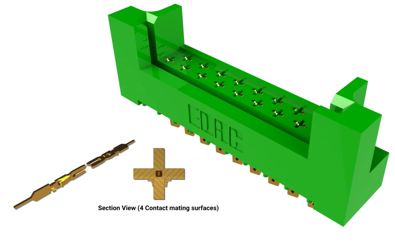
Figure 12: The hermaphroditic self-cleaning contact enables a connection with four contact-mating surfaces to create a gas-tight connection.
EDAC’s connectors for renewable energy applications
Renewable energy has already established itself as a major source of power in many nations globally. New installations continue to crop up, both onshore and offshore, creating new sources of renewable power that are fed directly into the power grid. These installations come with their own engineering considerations. Electric systems in outdoor environments will be exposed to a number of potentially damaging elements including rain, snow, hail, wind, salt atmospheres, and UV radiation. This can damage connections and cable runs that are not adequately ruggedized. EDAC offers several connectors that can be used within these applications that will operate despite the environmental and mechanical strain.
References
- Associated Press. (2023, March 28). US surpasses coal in renewable energy in 2022. AP News. https://apnews.com/article/renewable-energy-coal-n...
- Evolving Challenges of PV Cables and Connectors. UL. https://www.ul.com/insights/evolving-challenges-pv-cables-and-connectors.
- Offshore wind energy capacity worldwide from 2009 to 2022, Statista. 2023.
- Gipe, Paul. A Comprehensive Guide to Wind Power and How to Use It. Wind-Works Press, 2016.
Go Back

