Connector Systems – Architecture, Selection, and Design Guide
Connector systems form the foundation of modern electrical and electronic equipment, enabling reliable power, signal, and data transfer between subsystems. This engineering guide explains how electrical connector systems work at a system level—covering architecture, materials, reliability, sealing, and selection principles—to help designers choose the right interconnect strategy before narrowing into specific connector families.
What is a Connector System?
A connector system is more than the sum of its parts. While individual components—terminals, housings, seals—can be specified independently, true reliability emerges only when these elements function as a unified electromechanical assembly. The system encompasses the mating pair (plug and receptacle), contact terminals, housing insulation, retention mechanisms like Terminal Position Assurance (TPA) and Connector Position Assurance (CPA), and sealing components that work together to maintain electrical and mechanical integrity under real-world conditions.
System-level thinking matters because failures rarely occur in isolation. A housing with inadequate creepage distance can arc under contamination. A terminal with insufficient normal force may suffer fretting corrosion from vibration-induced micro-motion. A seal that lacks proper venting can breach during thermal cycling. Understanding these interactions—how normal force, wipe distance, strain relief, and thermal management integrate—is essential for designing reliable interconnect systems.
For detailed product families and form factors, explore:
Board-to-Board
Direct PCB interconnects for stacking, mezzanine, and high-density signal or power transfer between boards.
Learn More →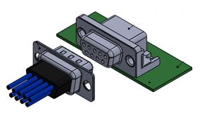
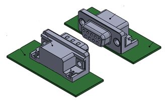
Wire-to-Board
Detachable cable-to-PCB connections supporting discrete wires, ribbon cable, and mixed signal/power harnesses.
Learn More →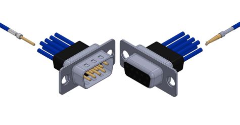
Wire-to-Wire
Inline cable connections for power and signal routing where no PCB interface is required.
Learn More →
Connector System Architecture
Contact Physics and Normal Force
Electrical conduction occurs through microscopic contact points known as a-spots—tiny asperities where metal-to-metal contact is established. Stable normal force is required to maintain these contact points and break through oxide layers, particularly with tin-plated terminals. Insufficient force increases resistance and promotes intermittent behavior over time. Connector systems must preserve this force through vibration, temperature cycling, and material relaxation across the product lifecycle.
Housing and Dielectric Design
The housing provides both mechanical alignment and dielectric strength. Materials are classified by Comparative Tracking Index (CTI), which determines resistance to surface tracking under contaminated conditions. CTI group directly influences voltage rating and creepage requirements. Higher pollution environments demand greater surface distances and higher-performance materials to prevent dielectric breakdown.
Retention and Assurance Mechanisms
Modern connector systems employ layered retention strategies. Terminal Position Assurance (TPA) prevents terminal back-out and verifies seating, while Connector Position Assurance (CPA) prevents accidental unmating. Primary latches provide baseline holding force, and secondary locks increase retention for vibration and harness loads. Together these mechanisms ensure long-term mechanical stability.
Sealing Architecture
Sealed systems typically use elastomeric grommets or concentric compression seals between mating halves. Seal performance depends on compression set, housing tolerances, and proper venting to avoid pressure differentials during thermal cycling. Effective ingress protection results from the entire mated assembly—not just the seal material alone.
Electrical Selection Considerations
Current Rating and Derating
Current ratings are specified at a defined temperature rise, commonly 30°C or 55°C above ambient. In multi-circuit systems, thermal coupling between adjacent contacts reduces available capacity. Derating curves must therefore be applied whenever multiple circuits carry load simultaneously to prevent overheating and premature aging.
Creepage and Clearance
Clearance is the shortest air path between conductors, while creepage is the path along the insulator surface. Creepage requirements depend on pollution degree and material CTI. High-voltage connector systems—such as EV or energy storage applications—often require substantial spacing to prevent flashover. Voltage class and environment must always be evaluated together.
Contact Resistance and Signal Integrity
Contact resistance, typically measured in milliohms, affects both power efficiency and signal performance. Dry circuits demand extremely stable resistance, while power circuits must account for I²R heating and voltage drop. Resistance drift over time is driven by oxidation, fretting, and loss of normal force.
Mechanical Reliability and Vibration
Mechanical stress is often the primary driver of connector failure. Standards such as USCAR-2 classify vibration severity by installation location, ranging from low-vibration chassis environments to extreme wheel-hub exposures. Connectors must be selected according to the expected profile to avoid premature intermittency.
Fretting corrosion caused by micro-motion degrades plating and increases resistance, especially in tin systems. Adequate retention force, reduced movement, and appropriate plating selection mitigate these effects. Mating durability must also match service frequency—gold plating supports higher cycle counts than tin.
Environmental and Sealing Design
Environmental exposure defines sealing requirements. IP67 protects against dust and temporary immersion, IP68 supports continuous immersion, and IP69K withstands high-pressure washdown. These ratings apply to the complete connector system including housings, seals, and cable entry points.
Corrosion testing such as salt spray evaluates plating and seal integrity. Temperature classes—from standard consumer to under-hood automotive—must account for both ambient heat and self-heating. Material and seal selection directly determine long-term reliability in harsh environments.
Materials and Plating Selection
Plating selection balances cost, conductivity, and durability. Tin offers economical performance with sufficient force. Gold provides stable low-resistance contacts for signal and low-current circuits. Silver supports high-power transfer but requires environmental consideration. Housing materials such as PBT or nylon provide mechanical strength and chemical resistance, often with UL 94 V-0 flammability ratings for safety compliance.
Termination and Assembly Methods
Crimp terminations create gas-tight cold welds that deliver excellent vibration resistance and are preferred for most production harnesses. IDC supports rapid mass termination for ribbon cables but is generally suited to lower-stress environments. Proper strain relief is essential to prevent mechanical loads from degrading contact force or seal performance.
Standards and Certifications
Connector systems are validated through industry standards. UL 1977 addresses safety requirements for component connectors. IEC 61984 defines international safety and test criteria. USCAR-2 and LV 214 specify automotive performance testing including vibration, sealing, and electrical cycling. EIA-364 provides the individual test methods referenced by these specifications.
Connector System Selection Framework
A structured selection process simplifies design:
- Define electrical load and voltage class
- Match environmental and IP requirements
- Evaluate vibration and mating cycles
- Select termination method
- Confirm applicable standards and certifications
Once requirements are defined, choose the appropriate connector architecture: Board-to-Board, Wire-to-Board, or Wire-to-Wire.
Designing Reliable Interconnect Systems
Reliable electrical connector systems result from coordinated design across contacts, housings, retention, and sealing. By applying system-level engineering—considering thermal limits, mechanical stress, environmental exposure, and standards compliance—designers can build interconnect solutions that maintain performance throughout the product lifecycle.